Page 57 - Physics - XII
P. 57

Principle/Theory

          In household circuit, all appliances are connected in parallel with mains. Consider P , P , P ,P , P , ... be the
                                                                                                       4
                                                                                                          5
                                                                                                    3
                                                                                             1
                                                                                                2
          power consumed by diff erent domestic electrical appliances in a circuit. Then, the total power consumed
          at any instant is given by
                                     P = P + P + P +P + P + ...
                                                    3
                                           1
                                                        4
                                                            5
                                               2
          At a potential V, the current I drawn from the mains is given by
                                         P
                                     I =   , where P is in watt, I is in ampere and V is in volt.
                                         V
          In the case when the terminals of electric appliances get accidentally connected, a high current is down
          from the circuit which may damage the appliances. A fuse of rating little higher than the current drawn is
          connected in series with the appliances.
          Procedure

          1.  Take three bulbs B , B , and B  and connect them in series with switches S , S , and S  respectively.
                                 1
                                     2
                                                                                            2
                                                                                                    3
                                             3
                                                                                         1
          2.  All the connection must be parallel with each other.
          3.  Connect a fuse in series with the set up and connect a plug and socket at the end two leads. Also,
              connect a wire from the earth pi of the plug.
          4.  Insert the plug in socket provided in the main electric board.
          5.  Put the switches S , S , and S  ON one by one and observe the bulb glowing independently of the other
                                           3
                                 1
                                    2
              bulb.
          6.  Put all the switches ON simultaneously and observe the bulbs glowing together.
          Result

          Household circuit connection is complete and installed with safety.

          Precautions

          1.  The safety fuse should be suitably selected.
          2.  Be careful while working with the mains.


                                                      ACTIVITY - 4
          Aim
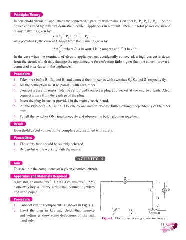
          To assemble the components of a given electrical circuit.

          Apparatus and Materials Required                                           A

          A resistor, an ammeter (0–1.5 A), a voltmeter (0 – 5V),                 +     –
          a one-way key, a battery, a rheostat, connecting wires,                                                +
          and sand paper                                                                              R           V
                                                                                                                 –
          Procedure

          1.  Connect various components as shown in Fig. 4.1.                                            Rh
          2.  Insert  the  plug  in  key  and  check  that  ammeter          +   –
              and voltmeter show some defl ections on the right                E          K            Rheostat
              hand side.                                              Fig. 4.1:  Electric circuit using given components
                                                                                                              55
   52   53   54   55   56   57   58   59   60   61   62